 Add Components
The Reliability Block Diagram drawing elements that are located in the toolbar are called shapes. The term component refers to a shape that represents a constituent part of the system.
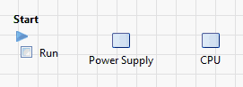
1. Click the Basic icon  on the Shape toolbar and drag the shape to the System Diagram to the right of the Start block.
2. Select the label, replace New Basic 1 by Power Supply, and press Enter.
Figure 11.3 Basic Shape

When you click the label or the shape, connection arrows appear. The arrows disappear when you click elsewhere in the template.
3. Drag a second Basic shape to the right of the Power Supply shape.
4. Select the label and type CPU.
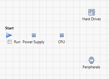
Figure 11.4 Example System Diagram
Note: You will align the shapes later, in the section Align Shapes.
5. Drag a Parallel shape  to a position to the right and below the CPU shape.
6. Select the label and type Peripherals.
7. Drag a K out of N shape  to a position to the right and above the CPU shape.
8. Select the label and type Hard Drives.
Figure 11.5 Partial System Diagram
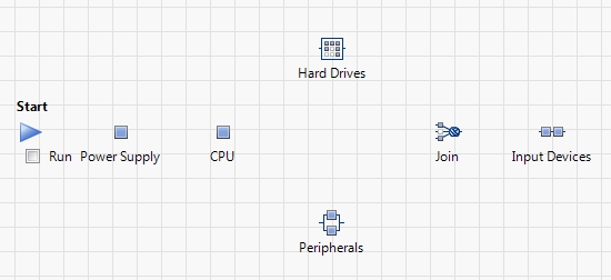
9. Drag a Knot shape  to the right of the previous shapes.
10. Select the label and type Join.
11. Drag a Series shape  to a position to the right of the Knot shape.
12. Select the label and type Input Devices.
Figure 11.6 Partial System Diagram
13. Drag a Basic shape to a position to the right of the Input Devices shape.
14. Select the label and type Monitor.
Figure 11.7 System Diagram Showing All Shapes
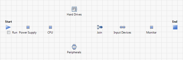
15. Proceed with Align Shapes.