Response Surface Design With Constraints and Categorical Factor
In this example, you create a design to optimize the yield of a chemical reaction. Your experimental factors include a categorical factor at three levels, where constraints involve two of the levels. In this example, you will use the Disallowed Combinations Filter to enter the constraints.
Your response is Yield. Your factors are the following:
• Time: The range of interest is 500 to 560 seconds.
• Temperature: The range of interest is 350 to 750 degrees Kelvin.
• Catalyst: Three catalysts A, B, and C, must be tested.
Your design must allow for constraints on two of the levels of Catalyst:
• When catalyst B is used, the temperature must be above 400.
• When catalyst C is used, the temperature must be below 650.
Define the Response and Factors
1. Select DOE > Custom Design.
2. In the Response outline, double-click Y and change it to Yield.
Because your goal is to maximize Yield, leave the Goal set to Maximize.
3. In the Factors outline, type 2 next to Add N Factors.
4. Click Add Factor > Continuous.
5. Click Add Factor > Categorical > 3 Level.
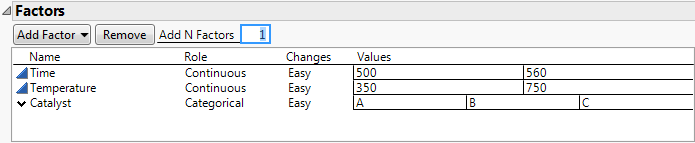
6. Rename the factors Time, Temperature, and Catalyst.
7. Change the Values for Time to 500 and 560.
8. Change the Values for Temperature to 350 and 750.
9. Change the Values for Catalyst to A, B, and C.
Figure 5.46 Factor Settings
10. Click Continue.
Define the Constraints
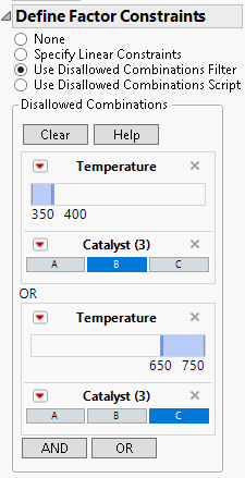
1. Select Use Disallowed Combinations Filter in the Define Factor Constraints outline.
2. Select Temperature and Catalyst from the Add Filter Factors list.
3. Click Add.
4. Click 750 in the equation that appears above the Temperature slider and change it to 400. Press Enter (or click elsewhere).
This disallows factor settings with Temperature values below 400.
5. Click the B block under Catalyst.
Together with the constraint on Temperature, this disallows factor settings for which Catalyst is B and Temperature is below 400.
6. Click OR.
This allows you to define your second constraint.
7. Select Temperature and Catalyst from the Add Filter Factors list. (Your earlier selection may have been retained.)
8. Click Add.
9. In the panel that appears beneath the word OR, click 350 in the equation that appears above the Temperature slider and change it to 650. Press Enter (or click elsewhere).
This disallows factor settings with Temperature values above 650.
10. Click the C block under Catalyst.
Together with the constraint on Temperature, this disallows factor settings for which Catalyst is C and Temperature is above 650.
Figure 5.47 Constraints Defined
Add Response Surface Terms and Make Design
1. In the Model outline, select RSM.
A JMP Alert informs you that only quadratic terms for continuous factors are being added to the model.
2. Click OK to dismiss the alert.
JMP adds only the appropriate response surface terms to the model.
Note: Setting the Random Seed in step 3 and Number of Starts in step 4 reproduces the exact results shown in this example. In constructing a design on your own, these steps are not necessary.
3. (Optional) Click the Custom Design red triangle, select Set Random Seed, type 654321, and click OK.
4. (Optional) Click the Custom Design red triangle, select Number of Starts and set it to 1000. Click OK.
5. Click Make Design.
Figure 5.48 Design Satisfying Constraints
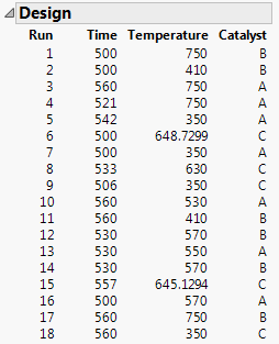
Because you added RSM terms to the Model outline, this is an I-optimal design. It satisfies your constraints:
– When catalyst B is used, the temperature must be above 400.
– When catalyst C is used, the temperature must be below 650.
View the Design
Recall that the design region consists of settings of Time between 500 and 560 and Temperature between 350 and 750. To obtain a geometric view of the design points within the design region, do the following:
1. Click Make Table.
2. Select Graph > Graph Builder.
3. Select Time and Temperature and drag them to the center of the template.
4. Deselect the Smoother icon. This is the second icon from the left above the template.
5. Select Catalyst and drag it to the Group X zone at the top of the template.
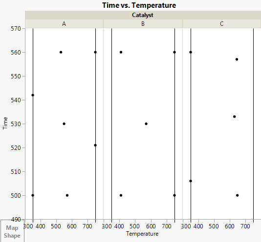
Figure 5.49 Design Points for Three Levels of Catalyst
6. Double-click the Temperature axis.
7. Under Reference Lines, do the following:
– Next to Value, enter 350.
– Click Add.
– Next to Value, enter 750.
– Click Add.
8. Click OK.
Figure 5.50 Design Bounds on Temperature for Three Levels of Catalyst
9. Double-click the Time axis.
10. Under Reference Lines, do the following:
– Next to Value, enter 500.
– Click Add.
– Next to Value, enter 560.
– Click Add.
11. Click OK.
12. Click Done.
Note: The plot in Figure 5.51 is vertically resized.
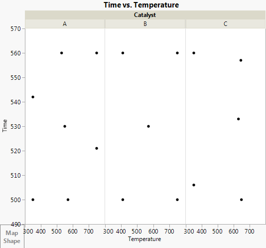
Figure 5.51 Design Regions for Three Levels of Catalyst
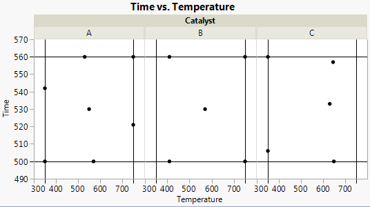
Six of the settings for Catalyst A fall on the edges of the design region. All Temperature setting for Catalyst B are above the 400 degree constraint and all Temperature settings for Catalyst C are below the 650 degree constraint.