Create the Design
The factors and their settings are given in the data table Phone Factors.jmp. Create a Strength 2 covering array by following these steps.
 Load Factors
1. Select Help > Sample Data Library and open Design Experiment/Phone Factors.jmp.
The Phone Factors.jmp data table contains the factors and their settings.
2. Select DOE > Special Purpose > Covering Array.
Notice that the menu next to Strength: t = , is set to 2 by default.
3. Click the Covering Array red triangle and select Load Factors.
The Factors outline is populated with the five factors and their levels.
Figure 20.10 Factors Outline for Phone Factors
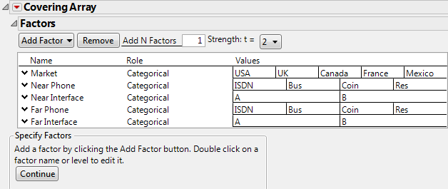
4. Click Continue.
The Restrict Factor Level Combinations outline opens.
 Restrict Factor Level Combinations
You can specify disallowed combinations in two ways:
• Use Disallowed Combinations Filter
• Use Disallowed Combinations Script
The filter gives an intuitive way to specify disallowed combinations. The script provides a quick and easy way to specify disallowed combinations, but requires that you have written or saved a script. In this example, if you do not want to specify combinations using the filter, skip to Specify Disallowed Combinations Using a Script.
Recall that the restrictions are the following:
• An ISDN line on either phone (Near or Far) cannot use interface A.
• Business and Residential phones on the originating phone (Near) cannot use interface B.
 Specify Disallowed Combinations Using the Filter
Use this approach to enter disallowed combinations using the filter interface. Alternatively, you can paste a script as shown in Specify Disallowed Combinations Using a Script.
1. Select Use Disallowed Combinations Filter.
2. From the Add Filter Factors list, select Near Phone and Near Interface and click Add.
3. Hold down the Ctrl key and click ISDN under Near Phone and A under Near Interface.
Figure 20.11 Disallowed Combinations Panel Showing First Constraints
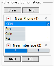
Both blocks should turn dark. You have added the constraint that an ISDN line on the originating phone (Near) cannot use interface A.
4. Click OR.
5. From the Add Filter Factors list, select Far Phone and Far Interface and click Add.
6. Hold down the Ctrl key and click ISDN under Far Phone and A under Far Interface.
You have added the constraint that an ISDN line on the receiving phone (Far) cannot use interface A.
7. Click OR.
8. From the Add Filter Factors list, select Near Phone and Near Interface and click Add.
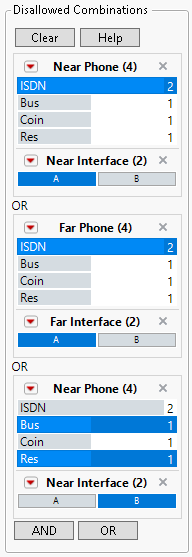
9. Hold down the Ctrl key and click Bus and Res under Near Phone and B under Near Interface.
You have added the restriction that Business and Residential lines on the originating phone (Near) cannot use interface B.
Figure 20.12 Completed Disallowed Combinations Filter
 Specify Disallowed Combinations Using a Script
Alternatively, you can specify disallowed combinations by constructing a script. After loading your factors (Load Factors), do the following:
1. Click Continue.
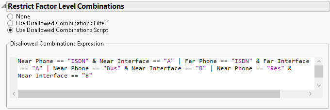
2. Select Use Disallowed Combinations Script.
3. Copy the following script and paste it in the Disallowed Combinations Expression script box:
(Near Phone == "ISDN" & Near Interface == "A") |
(Far Phone == "ISDN" & Far Interface == "A") |
(Near Phone == "Bus" & Near Interface == "B") |
(Near Phone == "Res" & Near Interface == "B")
Figure 20.13 Completed Disallowed Combinations Script Window
 Construct the Design Table
Note: Setting the Random Seed in the next two steps reproduces the exact results shown in this example. When constructing a design on your own, these steps are not necessary.
1. Click the Covering Array red triangle and select Set Random Seed.
2. Enter 632 and click OK.
3. Click Make Design.
The Design outline opens to show a 20-run design. A Metrics outline is added to the window.
Figure 20.14 Metrics Outline for Phone Design
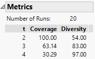
The Metrics outline indicates that Strength 2 coverage is 100%. This means that all permissible two-factor combinations are represented in the design. The design also covers 65% of all three-factor combinations.
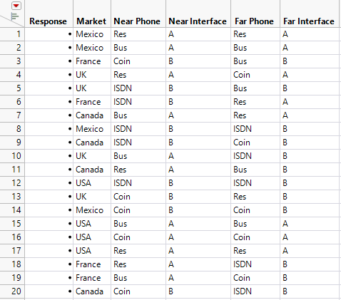
4. Click Make Table.
The design is placed in a design table. A column for the response is provided, as well as various scripts.
Figure 20.15 Covering Array Design Table